On a hunch I went to the garage where the 11/45 is sitting and checked out the BA-11 expansion box that was part of that system (which I was not going to use once I got the 11/45 going). What luck! It was a BA-11KE! So it looked like I could put together an 11/05.
So I sent the money, and a week later a box showed up with the bits of the 11/05 in it. At this point you're asking yourself, "he bought the parts for an 11/05 but this page is for an 11/10. What gives?" Well as I was unpacking the parts, I unpacked the console, and it said PDP-11/10 on it. The fact is that the 11/05 and 11/10 are the same computer with different badging (it's all the same inside). One was intended for use by end customers and one for OEMs.
So the first activity was to gut the BA-11 of all of the boards and system units (these have been saved don't worry). I then installed the 11/05 err 11/10 backplane and one DD-11C system unit (both being empty). Now for the first "smoke test". The BA-11 was plugged into the wall and its circuit breaker turned on -- no smoke, no sparks -- so far so good. Turned everything off. Reposition the BA-11 to get a better angle to get a voltmeter in and check all the voltages. Turned everything back on, all voltages look OK. I'm about to power it down and the most impressive set of sparks jump out from the bottom of the power supply -- great! Quickly everything gets turned off and that wonderful smell of burnt electronic componentry fills the air of my home office.
Time to pull the power supply out of the BA-11 and see how fatal this
is. As I'm repositioning the BA-11 to get at stuff a bit better and
a little nut falls out from one of the voltage regulators (note
to self: check all parts especially power supplies for stray bits from
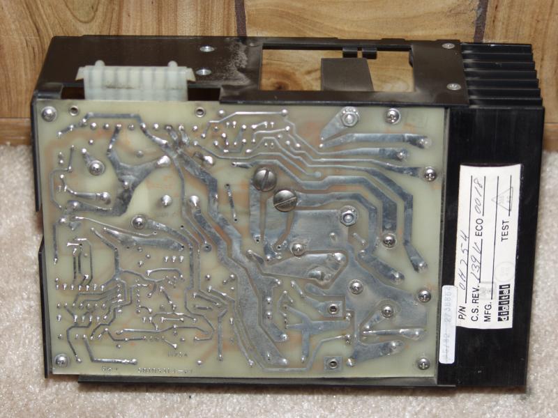
now on). I get the power supply fully disassembled and the individual
regulators out. As I'm looking over the various parts for obvious
damage, I get to the H754 regulator (+20v, -5v) and notice that there is
a 0.5" gap in two of the traces with a good amount of scorching.
It turns out that the regulators in the BA-11 are the same as those used by the H742's in the 11/45. The fellow I got the 11/45 was nice enough to send a number of spare regulators. Now did I have a spare H754 and did that one work? Luck was still with me on this and there was an extra H754 and it did work.
I put the power supply back together and powered the BA-11 back up. A check of the voltages indicated that they were all fine (and on the right pins of the backplanes -- even better).
I discovered that there was one thing I didn't have. That was
the harness that powered the front panel and controlled the power supply
from the key switch on the front. A while later after some lengths
of wire, heat shrink tubing, spade connectors and some solder a proper
harness was constructed. With just the front panel hooked up (no
boards in) it was time to see if the harness was correct. Plugged
it in, turned on the breaker...and nothing...oh yeah, turn the key to "on".
Power supply turned on and the front panel had the right voltage.
Turn key to "off" and it turned off! OK we're making progress.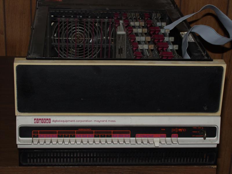
Flushed with success, it was time to go for broke. Consulting the various 11/05 documentation, all of the boards went into their proper locations in the backplane. Now for the moment of truth (the guy I got this stuff from didn't know if any of it was any good). Turned it on, fans wirred and lights...didn't blink. Hmm, OK, it's halted -- yes halt/enable switch is "halt". Let's try loading and address, flipped a couple of the front panel switches and hit load address -- cool the address was loaded. Let's try loading a value...yep that works too. Keep hitting the "dep" switch and the address increments as values are being stored.
Enough fun and games. It's a computer...compute! I realize it's been a loooong time since I bit-twiddled a PDP-11 program, so let's go for something real simple -- a two instruction loop (NOP and branch). To make sure I'm not fighting with potential core memory problems, I'm going to store and run the program in R0 and R1 (ain't old computers cool?).
I set the address to 177700 and load 000240 followed by 000777. Set the address back to 177700, put the halt/enable switch to enable and hit "start". Cool, lights blink and the run light is on! Hit halt, and repeatedly hit continue. I can see it execute 2 whole instructions!!!
Well with Christmas and all I don't have much more time to play with
it. But the first of my PDP-11s seems to be somewhat "alive".
I just performed one more check to make sure that it was the core memory
and not something to do with the processor (or the unibus backplane itself).
I put the M873-YA boot strap board back in and checked its contents.
They all looked good. So it does really look like there's a problem
with the core memory.
Just to satisfy my desire to know how bad things might be, I decided to take one of the 64KW memory boards out of my 11/45 and put it in the 11/10 to see if it really was related to the core memory. It was a success! I could read and write locations in the MOS memory and the values that I read out were the values that I had stored in it.
The core memory is composed of 4 boards:
| G235 | 16K X-Y Drivers |
| H217-C | 16KW core stack |
| G114 | 16K Sense/Inhibit |
| M8293 | 16K Unibus Timing |
I've located some G114 and G235 boards. They should arrive sometime
next week. The H217-C core stack is some what expensive, so I'll
see if replacing one of the other boards solves the problem. I have
been unable to locate an M8293, so I'm hoping that isn't the problem.
I also found an M7847 (16KW MOS memory) that I was planning using to expand
the amount of memory. But if I can't get the core to work, it looks
like that might solve the memory problem.
I'm now off to figure out how to disable the SLC on the CPU board and
use something a bit more rational (like an M7800 or an M7856). Then
I'd have a stable SLC and not have to worry about adjusting pots to get
the baud rate right. Now if I could only find a nice set of RX02's...
It worked great! Characters were showing up on the terminal! Now if I could just figure out how to disable the console on the CPU.1000 5000
12701
176534
105711
100376
110061
2
5200
137
1006
Upon further examination, it may not be necessary to disable the SLC
on the CPU. It turns out that the connector that brings out the 20ma
current loop also brings out a few other "interesting" signals. Two
are TTL compatible signals for serial in and serial out to the UART.
This means that I can put a level shifter in and get RS-232 (EIA) signals
out. There are two other signals that are of interest on this connector.
One is an external clock for the SLC. The other allows the internal
serial clock to be disabled. OK, I've found a baud rate generator
that would work (M14144). The connector also brings out +5v so everything
is there that I need to build a converter and get resonable bit rates out
of it. Now I just have to start scrounging parts.
It was now time to locate the infamous W1 jumper and install it. Unfortunately DEC in their infinite wisdom chose not to make the location of this jumper obvious. After some searching with an ohmmeter and the schematics, I found were it should go and installed it. The system was powered up to make sure that I didn't screw anything up (I didn't).
Now that everything worked as before, I took out the M7800 and changed it's jumpers so that it was now located at the console's address and interrupt vector. I changed the test program above so that the address was now 177564 (the default console address) and output was being sent to the VT100.
I set the switches on the front panel to 173000 which is the start address of the high ROM which contains a console emulator of sorts. When I hit start, I was greeted with 4 6 digit octal numbers followed by a '$' on the next line. Gee this looks familiar. All is good.
Now I have an 11/10 with a real console. All I have to do now
is start hooking up some devices to it. The current configuration
is shown below.
| Slot | Backplane |
|
|
|
|
|
|
|
1
|
|
|
|||||
|
2
|
|
||||||
|
3
|
|
|
|||||
|
4
|
|
||||||
|
5
|
|
||||||
|
6
|
|
||||||
|
7
|
|
||||||
|
8
|
|
||||||
|
9
|
|
|
|||||
|
10
|
|
|
|||||
|
11
|
|
||||||
|
12
|
|
||||||
|
13
|
|
|
|||||
The big problem in getting this going was the module untilization for the MF11-UP backplane. I finally found it in the "MF11-U/UP core memory maintenance manual". For some bizarre reason, in that manual, it shows the module utilization as viewed from the backplane. I took the 16K of core that was already in the 11/10 and with another set of boards, I moved it all into the MF11-UP backplane. I also had to jumper the second M8293 16K unibus timing board to be at 16K-32K in the address space.
I turned everything on and when I tried to check memory, the UNIBUS would hang. So after moving things around I figured out that when memory was in the MF11-UP backplane, it would hang the UNIBUS when accessed. I concluded that it was something with the backplane. Voltages were checked. Cards were put up on extender boards so signals could be probed. Nothing. Not a clue as to why it wasn't working other than it wasn't.
Then I had an idea. The backplane is an MF11-UP (the P is for parity). All of the core I had could support parity, but I didn't want to deal with parity issues right now. That couldn't be it! After having tried everything else, why not? So I put an M7259 parity control board in its place in the backplane. And it worked! Ok, I should have done the configuration that way from the start. It would have saved *many* hours of head scratching.
The memory supports interleaving, so I'll go and reconfigure the M8293's to be interleaved and that should improve performance (who am I kidding, this is a PDP-11 it's not supposed to be fast -- but I'll do it anyway).
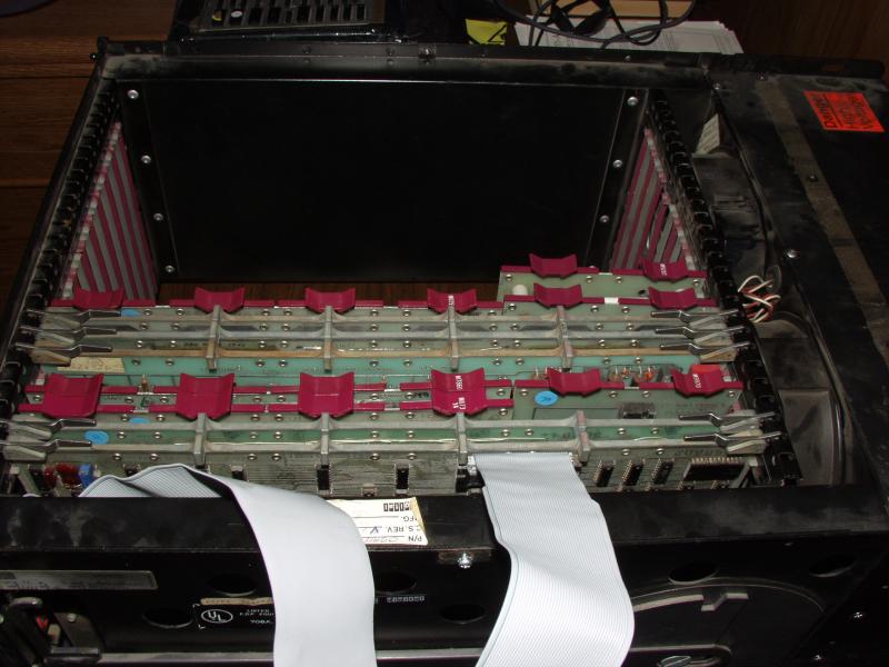
Here's a picture of the backplane with 32KW of core (28K usable).
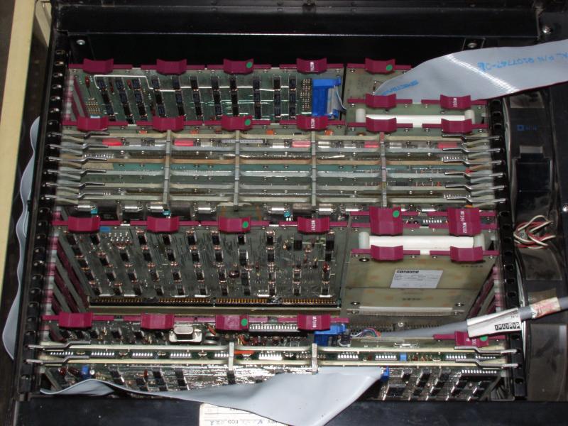
Here's the current module utilization.
| Slot | Backplane |
|
|
|
|
|
|
|
1
|
|
|
|||||
|
2
|
|
||||||
|
3
|
|
|
|||||
|
4
|
|
||||||
|
5
|
|
||||||
|
6
|
|||||||
|
7
|
|||||||
|
8
|
|||||||
|
9
|
|
||||||
|
10
|
MF11-UP | M8293 | |||||
|
11
|
M7259 | ||||||
|
12
|
G114 | ||||||
|
13
|
H217C | ||||||
|
14
|
G235 | ||||||
|
15
|
G235 | ||||||
|
16
|
H217C | ||||||
|
17
|
G114 | ||||||
|
18
|
M9202 | M8293 | |||||
|
19
|
|
|
|||||
|
20
|
|
||||||
|
21
|
|
||||||
|
22
|
|
M8256 | |||||
I've tried to boot the 11/10 from a floppy. I made it while testing
the RX02 drives on the 11/45. It should be a bootable version of
RT-11 but I can't seem to get it to do anything other than "click" the
floppy drive and then halt. I'm using a bootstrap
from one of the RT-11 manuals.