Not one to give up, I started looking for other sources for PDP-11's. After doing a search on Google, I found the classic computer mailing list (on Classic Computing ). There was a reference to someone who was selling a PDP-11/45. Figuring my luck couldn't be that good (it had to have already been sold after all the e-mail indicating that it was for sale was about a week old), I e-mailed the guy on the off chance that it was still for sale. To my amazement it was still available. What luck!
Then the reality set in. He wanted more than I really wanted to spend (all right *alot* more) for something I really didn't know what I was going to do with (other than I *had* to have it). After much thought and soul searching (aka rationalization) I went to the bank, got a money order and sent it overnight. Then the horror really set in. I had to have 2 19" racks totalling 1000 pounds shipped half way across the country. Eeek! Oh well, in for a penney, in for a pound (all puns intended).
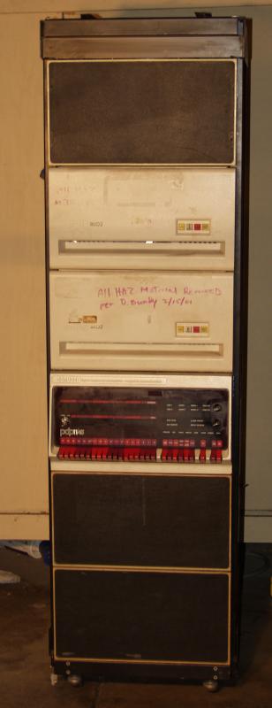
With much anticipation the 11/45 was crated and shipped. It
arrived on 12/11/02. Here it is with all of the packing material
off but still strapped down to the pallet.
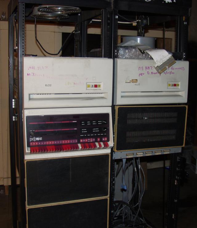
The '45 is pretty well configured:
The bad news was all of the cables had been cut. Including the BC-11A that connected the BA-11 to the 11/45. *sigh* On a positive note, I have been able to find many replacements on the web so they've been ordered and should arrive soon.
The other challenge was trying to figure out what type of power was needed by the 861-C power controller. All of the '45 documentation that I have indicated that there were two inputs:
120v 2 phaseI'd never heard of the first but I was planning for the worst since the 861-C indicated 120v 2 pole on its front. But upon further examination of the plug on the end of the cable and finding some more documentation, the 861-C requires *only* 120v at 24A (the plug is a 120v 30A plug). My plan is to not use the 861-C initially (until I make sure that the CPU works to some extent) and then figure out where and how to wire it up.
220v single phase
I've stripped off all of the cut cables and taken an inventory of
the cards in the 11/45 and the BA-11. Here's the result:
| Enclosure | Quantity | Card | Description |
| 11/45 | 1 | M787 | Line Frequency Clock |
| 1 | M8114 | 11/45 fraction high order data path module | |
| 1 | M8115 | 11/45 fraction low order data path module | |
| 1 | M8112 | 11/45 floating point ROM control module | |
| 1 | M8113 | 11/45 floating point exponent data paths module | |
| 1 | M8100 | 11/45 data path module | |
| 1 | M8101 | 11/45 general register address module | |
| 1 | M8102 | 11/45 instruction register control module | |
| 1 | M8103 | 11/45 ROM address control module | |
| 1 | M8104 | 11/45 processor data an unibus registers module | |
| 1 | M8105 | 11/45 timing and misc control module | |
| 1 | M8106 | 11/45 unibus control module | |
| 1 | M8108 | 11/45 segmentation status register module (KT11-C) | |
| 1 | M8107 | 11/45 segmentation address paths module | |
| 1 | M8109 | 11/45 timing generator module | |
| 2 | M7800 | DL-11 Async interface | |
| 1 | M9200 | unibus jumper | |
| 1 | M9202 | unibus connector | |
| 1 | M792-YD | Bootstrap loader | |
| 2 | ?? | 64KW Unibus MOS memory card | |
| BA-11 | 5 | M7800 | DL-11 Async interface |
| 1 | M7860 | DR11-C General Device Interface | |
| 1 | M7762 | RL11 RL01/02 disk drive controller | |
| 1 | ?? | Tape Controller | |
| 1 | M8716 | DR11-W General Purpose DMA parallel interface | |
| 1 | ?? | DMA parallel interface |
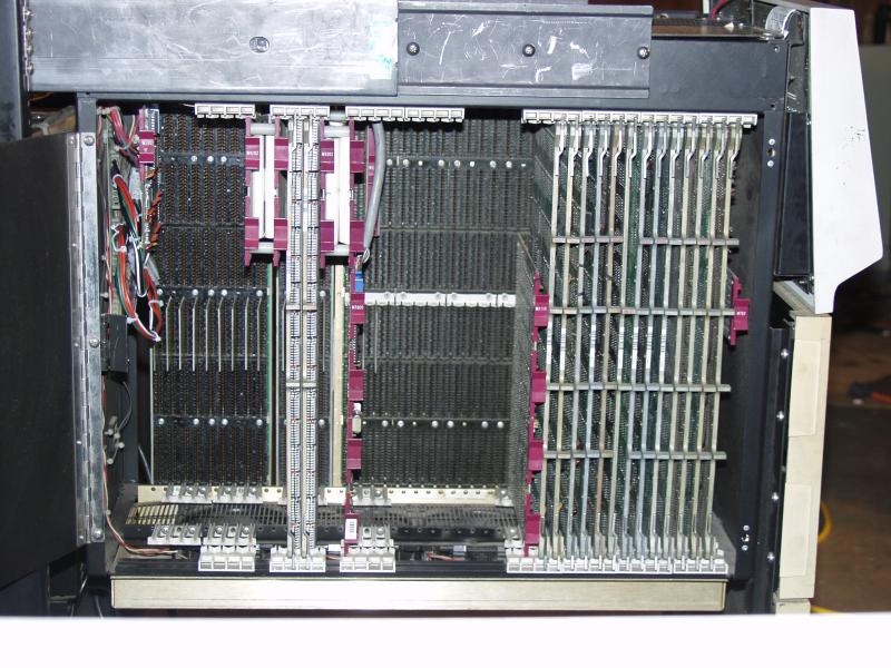
I plan on not using the BA-11. All of the cards I need can be
put into the 11/45 CPU cabinet (the only card I'll be moving over from
the BA-11 is the M7762 disk controller). However, since the 11/45
has only one system unit (4 unibus slots), I'll be taking the double
width system unit (9 unibus slots) out of the BA-11 and installing it in
the 11/45 eventually. Here's a picture of the 11/45 internals now.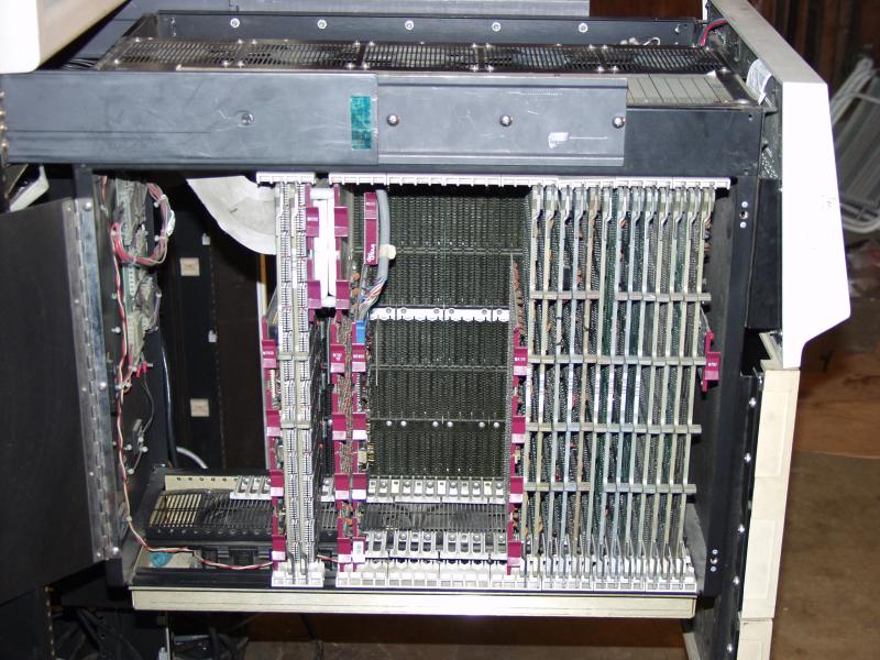
 Some friends came over and helped with
relocating the 11/45 and RL02 drives in the H960 cabinet. This
involved lowering the 11/45 in the H960 by 10.5". Prior to doing
that we had to move the H742 power supplies lower. This gave me
enough room in the H960 to put in the second RL02 drive at a reasonable
height.
Some friends came over and helped with
relocating the 11/45 and RL02 drives in the H960 cabinet. This
involved lowering the 11/45 in the H960 by 10.5". Prior to doing
that we had to move the H742 power supplies lower. This gave me
enough room in the H960 to put in the second RL02 drive at a reasonable
height.
Still haven't applied power yet. Maybe during the coming week.
Right now there's only a single system unit in the 11/45
chassis. I plan on putting in a dual system unit to allow me to
put some I/O in the 11/45 chassis. The 2 memory cards take up all
of the available hex slots in the single system unit, so I can't put in
any interesting controllers until I have more slots. The problem
is that since the 11/45 is s/n 242 (very early) it has an "old" style
power distribution board. None of the DD11's I have plug directly
into that distribution board (DEC fixed this on systems with s/n >
2000). So I have to go and wire up a harness to plug into the
power distribution board that the DD-11 can plug into.
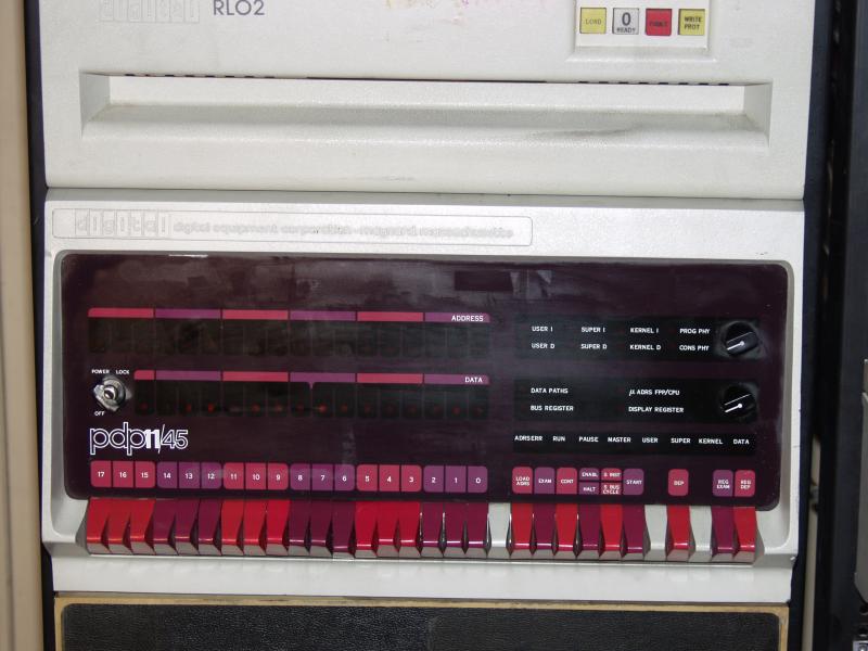
Now it was time to see if it could execute someone else's code. I removed the M930 terminator that was at the far end of the UNIBUS and replaced it with an M9301 bootstrap/terminator. After some messing about trying to determine what address I should get it to run at (773000 is the right answer) I got it to print out 4 sets of 6 octal numbers and then a '$' on the next line. Hmm. I was sort of expecting an '@'.
Figuring that there had to be something wrong with the M9301, I tried an M9312 (yes I set all of the W jumpers properly). That proved to be pretty pointless. Nothing I would do would get me to a prompt of any sort. I tried 765144 (which is what the reference manual said). I tried 773000. Nothing useful. Oh well. Back to the M9301.
After looking over the M9312 documentation, I decided that it was
worth a try to see if the '$' prompt was in fact the prompt for the
console emulator. It turns out that it was and I could use L, D, E
and S to set the load address, deposit values into memory, examine them
and start a program running. Wow! This is starting to act
like a real computer!
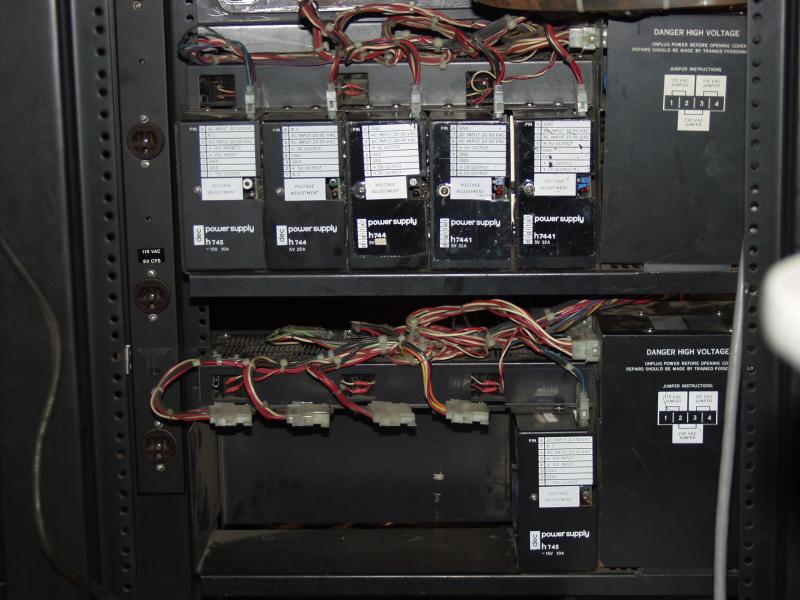
It was a tight fit but everything is hooked up with power and the backplane is now at the end of the 11/45's UNIBUS. So I now have plenty of slots to add in peripherals. At this point I'm not stressing the H744 +5v 25A regulator that supplies the system units. But if I start needing more, I can swap the H744 for an H7441 which provides 32A.
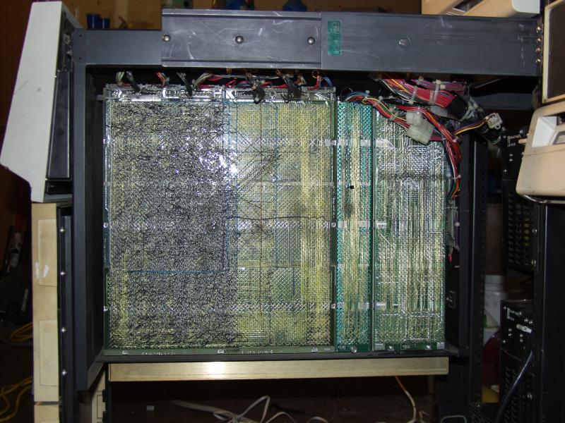
Here are a couple of shots of the 11/45 now with the DD-11 DK fit
in. Notice on the wirewrap side the jumble of power cables by the
DD-11 DK. That's why DEC repositioned the power distribution board
to the top next to the fans in systems with s/n > 2000.
Not having any luck I decided to go for broke and toggled in the bootstrap for VTserver (it's a really cool program). It downloaded the standalone copy program. For the source I entered vt(0,0,0) and for the destination I entered rl(0,0,1) which would theoretically load BSD 2.9 onto the RL02 pack.
Well it remained theoretical. I quickly got an error. Hmm. Seems like there's a problem with it reading/writing the drive. Hmm. Looking at the value for the status code it seems like it can't find headers from the drive. OK. I haven't ever run two drives together. Maybe it's a problem with the cabling so I remove drive 1 and retry. OK. This time the error is different. This time the error seems to be that the drive is not sensing write current from the head. This is bad. Damn. Down to one "good" drive.
As much as I want to continue, it's getting late so I'll tackle this
tomorrow.
After sending some frantic e-mails, I came up with an RL bootstrap here . I'm replicating it here as you can't have too many copies.
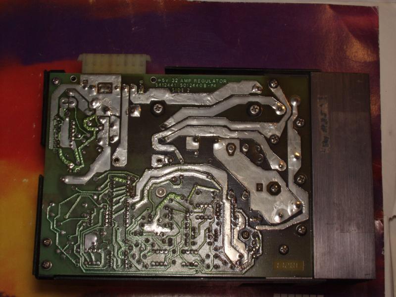
I was now ready to have my 11/45 run an OS. Back to the "machine room". I powered it up and was half way through toggling in the bootstrap when the 11/45 got weird. Uh-oh. This time it looked really bad. Fiddled around with it for a bit when that sinking feeling came back that I'd seen this before, except this was worse...much worse. So I pulled the 11/45 forward out of the rack and started probing voltages. +5v on the A regulator looked OK. I was having a really hard time getting a reading from the +5v on the B regulator. Hmm. It's not that hard to get the probes to make a connection on the backplane. Uh-oh. There is no voltage comming from the B regulator. This is the same regulator that was reading 4.4v. So I grab another H7441 regulator and I swap it out. Then I notice the burns on the PCB of the old regulator. It got cooked. I don't think it liked being powered on for almost 4 hours. With the new regulator, the 11/45 was happy once more.
I decided to try something a bit simple to start so I put an RT-11
pack into the drive. I toggled in the bootstrap and hit
start. On the terminal I saw RT-11 booting up! Yes!
It's running an OS. Well now it's really late so it's time to give
all of this stuff a rest. I'll see if I can't figure out how to
boot BSD tomorrow.
I left the M9301 at the end of the UNIBUS with its ROMs
enabled. There isn't an address conflict and if I ever want to use
the console emulator, all I have to do is load 773000 into the console switch
register.
Unix v7 I was only able to run in single user mode. It was a
copy of a pack that someone else had. It did boot, however I could
not get it to recognize that the terminal could generate
lower-case. I may go back and use vtserver to load up a pack with
a known v7 distribution on it and try that one. Like BSD, it does
produce an impressive display on the front panel when ever it did
anything.